 Computer Programming for primary education students in 21st century West Virginia!Computer Programming for primary education students in 21st century West Virginia!
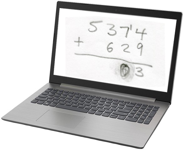
You’ve probably learned that computers work with binary numbers. Maybe you’ve heard “it’s all ones and zeroes”. These two states can also be thought of as on and off, or true and false.
|
In most modern computers, logic gates are generally made with semiconductors, and the two states are electrical voltage levels. These are low voltages, with very little current flowing. The output voltage is never entirely zero, so the two states are referred to as “low” and “high”.
 “Once upon a time” - in the 1940s and 1950s - logic gates were made with vacuum tubes, like the one shown at left. This made for some pretty bulky computers, like ENIAC, which was 8 ft × 3 ft × 98 ft in size. Development of semiconductor devices (transistors and diodes) made personal computers possible.
Since the 1960s, computers have become increasingly smaller and more powerful.
Compared to 1982, today's computers are over 100 times faster and over 100 times smaller.
But scientists say that semiconductor technology is approaching natural barriers to further miniaturization. The new hope is for molecular logic gates. Building a logic gate can get complicated, but they all perform the same function, and you don't need to know how one is made to understand how to use one.
|
Everything a digital computer does, it does by combining these two states with a few simple mechanisms known as “logic gates”.
Most logic gates take two inputs and combine them to give one output signal.
An “OR” gate gives a true result if either input is true.
 Click or tap on the "ON/OFF" switches to try them out!
 |
 |

|
|
 |
|
|
Real life examples of OR logic are:
An “AND” gate gives a true result if both inputs are true.
|
|

|
|
|
|
|
Real life examples of AND logic are:
An “XOR” (exclusive or) gate gives a true result if one, and only one, input is true.
|
|

|
|
|
|
|
Real life examples of XOR logic are:
Computers do arithmetic by using binary numbers:
Binary numbers use only 1 and 0, which can be expressed as true and false, as in this example of performing binary addition:
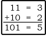 You do binary addition just like regular (base ten) addition, starting in the right most column (the ones place). In this example, 1 plus 0 equals 1, no carry. Move left one column, which instead of a tens column is the twos column, where a “1” means 1 two. 1 plus 1 equals two, written as 10, so we put a 0 in the twos place of our answer, and carry a 1. (The 1 we carry goes in the fours column, meaning 1 four. Our answer is 1 four plus 1 one, or 5.)
Let’s look at the above example again, where we add 3 plus 2 in binary. If we think of 1 as true and 0 as false, we can use logic to do addition.
If the first number has a 1 in the ones place OR the second number has a 1 in the ones place, BUT NOT BOTH, then the answer should have a 1 in the ones place.
If the first number has a 1 in the ones place AND the second number has a 1 in the ones place, then we have to carry 1 to the twos place.
So we can add the ones column of a binary addition problem with an XOR logic gate and determine whether or not we need to carry to the twos column with an AND gate. This is demonstrated by the logic circuit below, which is called a “half adder”. You can think of it as doing only half the job; it isn’t doing anything with the “carry” status.
In the twos column we have to add three values (the two addends plus the carry from the ones column), each of which can be 0 or 1 (false or true). So for that column, we need a “full adder”. Here, then, is the combination of the half adder plus the full adder to do addition of two 2-bit numbers. (Two bits can represent numbers in the range from 0 to 3.) The animation demonstrates several of the possible additions being performed.
If we wanted to add two 3-bit numbers, we would tack on another full adder circuit module for the third bit (the fours column), connecting the carry indicator output from the twos column to the carry indicator input of the fours column. And so on. Here is a 4-bit addition circuit performing some arithmetic:
The last 3 logic circuit images on this page are screen images of BOOLR.
BOOLR is a digital logic simulator. We are three Dutch high school students in our final year and we are doing a project about digital logic. To make our own digital logic circuits we have built BOOLR, which we have created with JavaScript and lots of love. BOOLR works with Windows, Mac OS and Linux and it is completely free.
You can download BOOLR and create your own logic circuits. You don't need to install it; just unzip it and run the executable: Boolr on Mac OS or Linux, BOOLR.exe on Windows.
To open a BOOLR .board file from someone else, you need to download or copy it to BOOLR's “saves” files. To do this, run BOOLR, click on “OPEN BOARD”, then click on “Open saves folder”. You can download the 4-bit addition circuit here. (You will probably need to right-click and choose “Save file...”.)
Or, if you’re on an Android or iOS device, or just prefer a web-based simulator, check out Logic Gate Simulator at Academo.